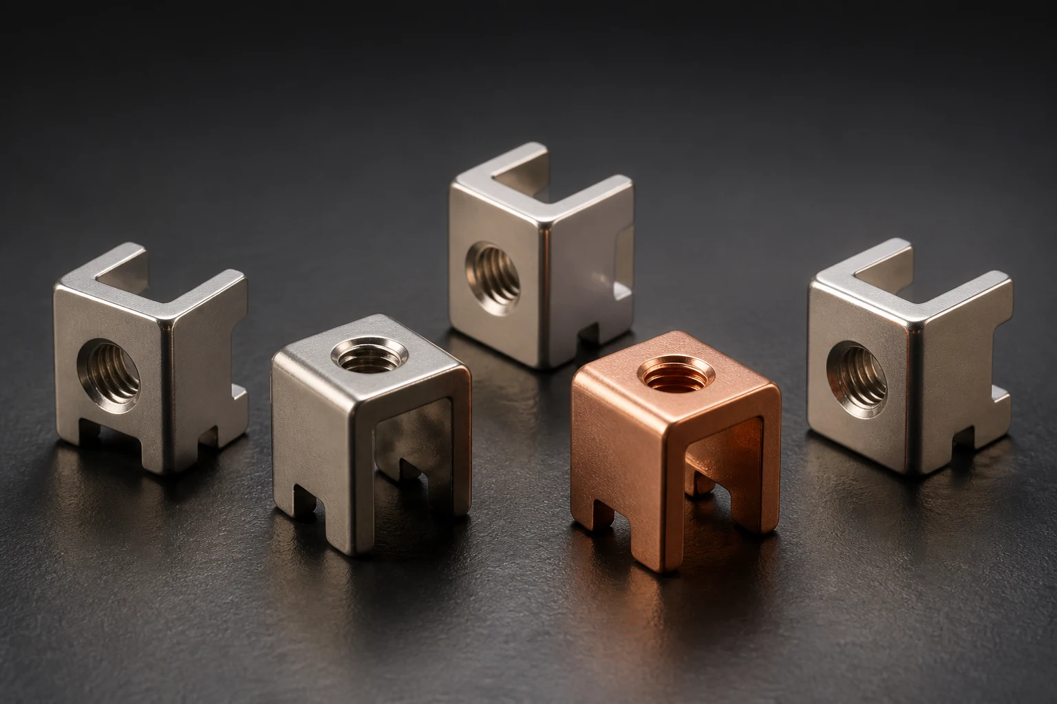
A PCB press-fit connection must match the terminal's press-in zone to the plated through-hole. IEC 60352-5:2020 provides a framework for mechanical, electrical and environmental testing of solderless press-in connections. The terminal and PCB supplier data still need to match the actual board thickness, hole size and insertion tooling. A part number alone does not prove the assembled joint.
Treat the terminal and plated hole as one system
An elastic press-in zone deforms within its design range during insertion and then maintains contact normal force. TE Connectivity describes compliant pins as working with the plated hole as a press-fit system. A change to hole size, copper plating, board thickness or terminal geometry can move the assembly outside its previously verified range.
The drawing review should lock the terminal and press-in zone, finished hole diameter and tolerance, copper plating, board material and thickness, insertion direction, edge distance, board support and press-head alignment. Use limits supplied for that terminal and board system.
Force-displacement records reveal more than a peak value
The 2020 revision of IEC 60352-5 refers to recording insertion and extraction force curves. Keep force versus displacement, insertion speed, tooling and support location, board revision and measured hole data with each test. A maximum force alone hides how the terminal enters the hole, develops contact and reaches its seated position.
Acceptance limits should come from the terminal specification and an approved application evaluation. Confirm the window with first articles and representative tolerance samples, then check that production equipment reproduces it. Do not transfer a curve from a different terminal or board thickness.
Tie mechanical and electrical results to the same specimens
Record contact resistance, terminal condition, board distortion and damage around the hole before and after insertion. Higher-reliability programs may add electrical retest and cross-section inspection after the specified temperature or corrosion exposure. IEC defines test methods for comparison; the product owner sets the application acceptance criteria.
Rework or a second insertion changes the terminal and hole interface. Manufacturing instructions should separately define removal, reuse and post-repair inspection rules.
- State finished-hole diameter, plating, board material, thickness and tolerance source
- Retain insertion and extraction curves with tooling calibration records
- Link resistance, damage and environmental results to specimen IDs
Include the press-fit system in the RFQ package
Submit the terminal drawing, PCB hole table, stack-up, target current and expected environment together. If the joint carries structural load or must be removed, state the load direction and service count. The supplier can then confirm the matching range and the application owner can approve a validation plan.
Apply this guide to a project
Use product pages to identify the hardware family and the calculator for early estimates only. Acceptance depends on drawings, operating conditions and project tests.