QSMT or through-hole?
The choice depends on current, mechanical load, board thickness, soldering equipment and takt time.
PCB SOLDER TERMINALS
High-current interfaces from a PCB to busbars, cables or equipment, covering through-hole, surface-mount, right-angle and custom soldered structures.
This page describes a product family and selection inputs. Confirm current rating, temperature rise, tolerances, certification scope and lead time against the selected part, drawing and valid records. Illustrations are not product or factory evidence. Cu-Al figures come from supplied material documents and apply only to their samples and conditions, not a blanket certification or system cost guarantee.
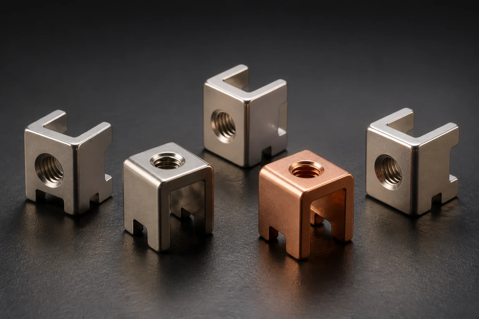
Standardized replacement models and customized dimensions tailored to your PCB footprint and thermal budget.
| Engineering Dimension | Specification & Standard |
|---|---|
| Product forms | Solder terminals, battery terminals and board-level posts |
| Mounting | SMT, vertical through-hole, right-angle and combined structures |
| Interfaces | Threaded holes, studs, crimp or solder interfaces |
| Finishes | Solderable or corrosion-resistant finishes by duty |
| RFQ inputs | Thread, body height, pins, torque, soldering process and volume |
Terminal structure and PCB layout review
Material, plating and soldering-window checks
Torque, attachment and assembly-boundary review
Prototype reflow and volume consistency planning
Board-to-busbar, sensing and power interfaces
High-voltage boxes and charging modules
Inverters, motor control and high-power supplies
The choice depends on current, mechanical load, board thickness, soldering equipment and takt time.
Yes. Start with space, interface, target current and load direction, then add drawings.
Share critical dimensions, target current, assembly conditions and volume to agree the DFM review scope and project schedule.