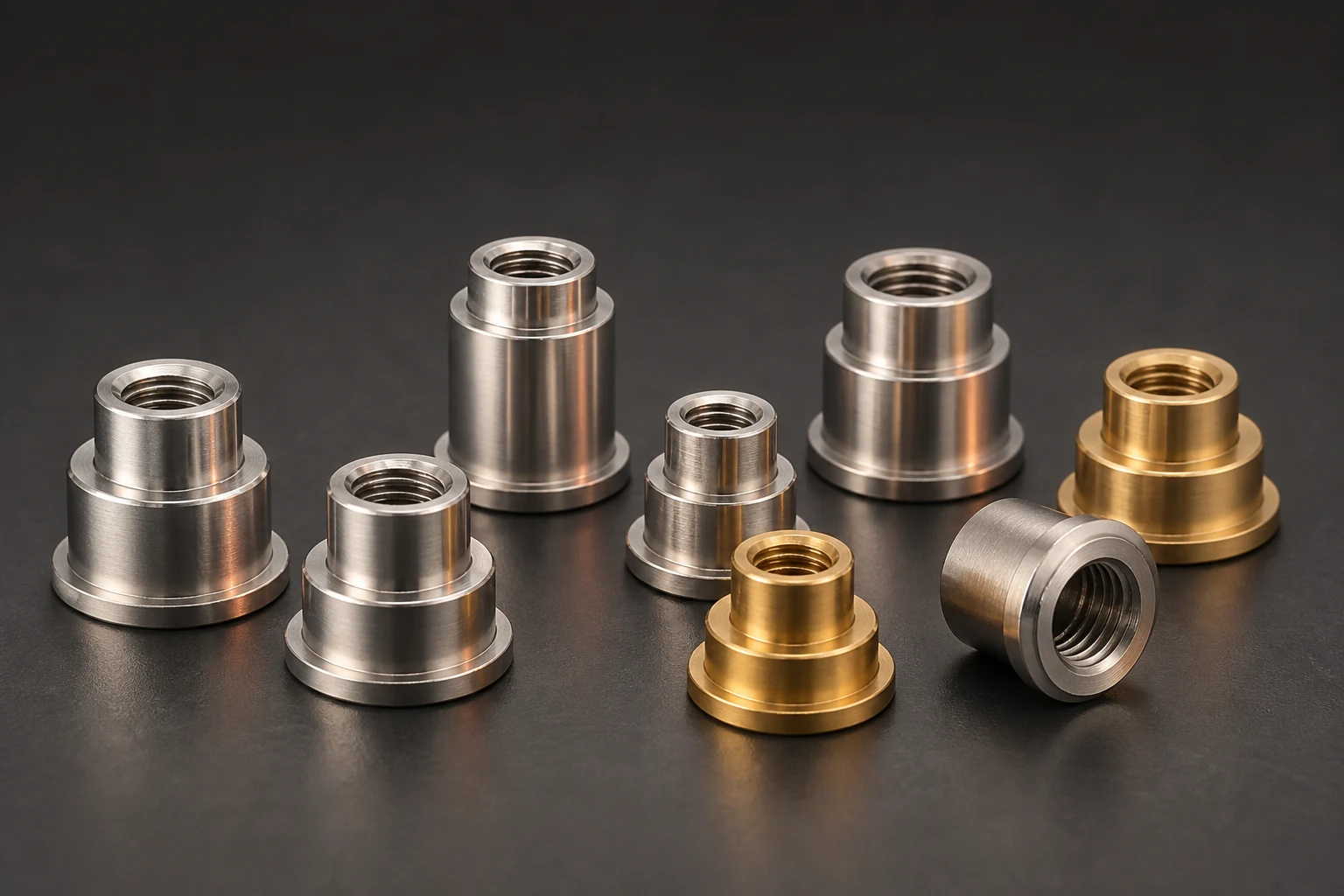
Define coated and prohibited regions by function before coating a PCB with SMT busbars, nuts or springs. Contacts, threads, test points and later solder areas cannot be identified from the part outline alone. Mark boundaries on assembly drawings and confirm them through the actual application and cure process.
Translate hardware functions into coating boundaries
Map contacts, spring working faces, thread engagement, test points and later solder surfaces against assembly steps. Have the product owner define keep-outs and permitted boundaries. Neither all-metal exclusion nor coating every surface is an appropriate default for interfaces needing direct contact.
Include undersides, holes and board edges. Establish where coating fits between soldering, testing and fastening. Review cleanliness, compatibility and cure separately; correct masking does not qualify the coating system.
Review holes and undersides despite selective application
HumiSeal explains that selective spraying can reduce masking but does not eliminate its need. Vias on double-sided boards may carry coating to underside features needing protection. Programmed spray paths alone do not establish final boundaries beneath hardware or inside holes.
Use representative boards to review nozzle paths, orientation, shadowing and migration routes. Check tape, plugs or temporary masks against coating, cleaners and curing, including residue or damage after removal.
Include mask removal and functional checks
Specify masking, application, cure, removal and inspection sequence. Retain first-article images and drawing coordinates. Check boundary encroachment, hole residue and missed coverage beneath hardware using methods suited to the actual material and product. Visible fluorescence alone does not prove adequate cure.
Under approved safe conditions, review test contacts, electrical interfaces and fastening functions. Do not release abnormal parts by forcing screws through coating. Record removal, cleaning, recoating and inspection during rework. Changed coating or hardware geometry requires boundary and program review.
- Map required coverage and functional keep-outs
- Confirm hole and underside migration on representative boards
- Record removal, boundary checks and functional review
Frequently asked questions
Does automated selective coating eliminate masking? Validate the actual board, especially holes and underside features.
Does successful screw insertion prove a clean thread? Apply the approved cleanliness and fastening checks rather than forcing assembly.
RFQ inputs for coating and hardware
Provide assembly drawings, functional faces, coating and cure conditions, keep-out coordinates and later testing or fastening requirements. Agree masking, first-article, removal and rework responsibilities. Review achievable boundaries before freezing supply and process requirements.
Apply this guide to a project
Use product pages to identify the hardware family and the calculator for early estimates only. Acceptance depends on drawings, operating conditions and project tests.