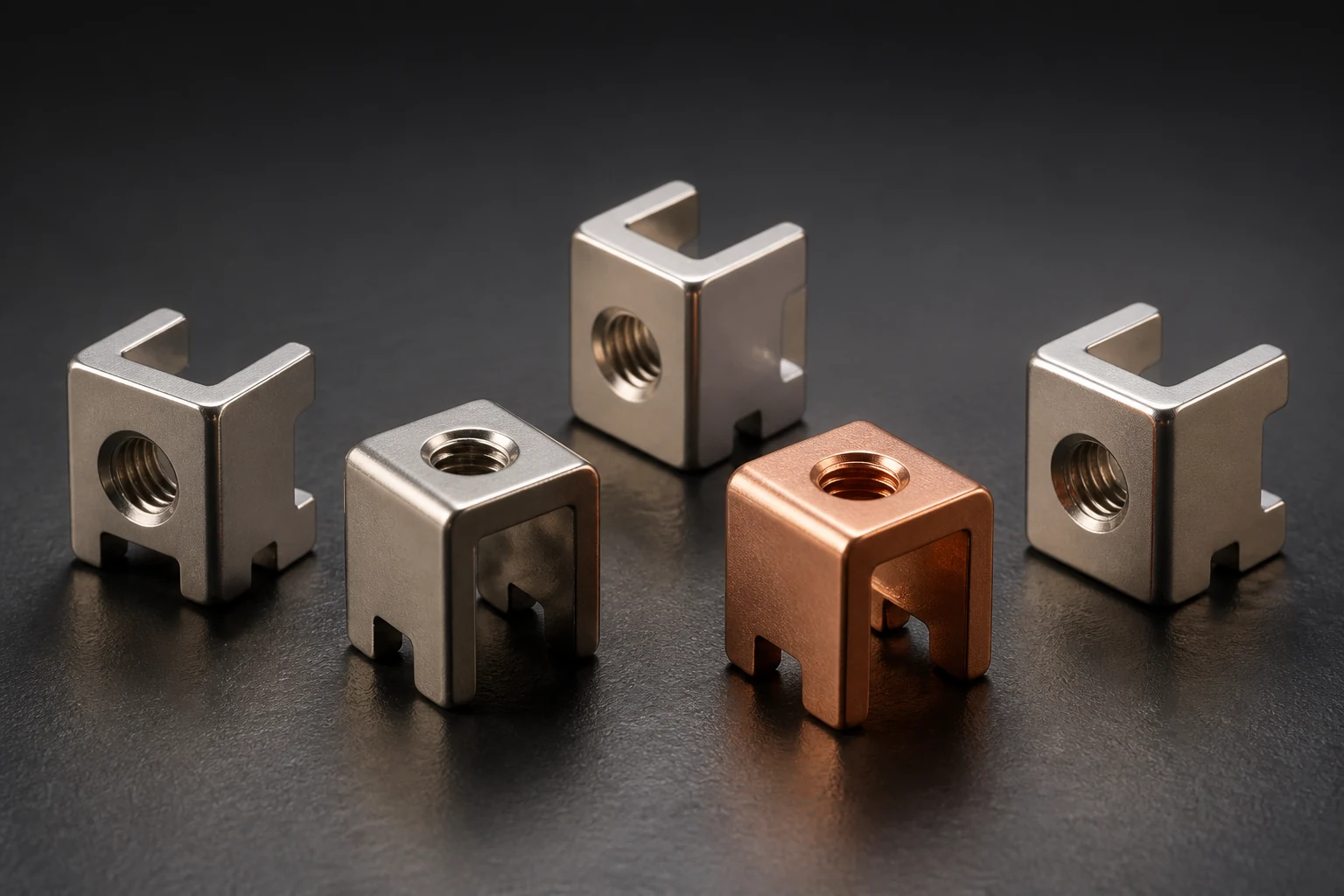
Confirm a PCB power terminal's suitability for through-hole reflow before reviewing finished holes, pins, board thickness and paste volume together. A standard through-hole part is not qualified for reflow merely because its metal tolerates heat. Surface-pad stencil designs do not transfer unchanged to pin-in-paste assembly.
Review pins against finished-hole tolerances
Phoenix Contact identifies pin geometry, hole size and board thickness as important THR process-window inputs. Use the specific terminal drawing to review finished plated holes, pin section and position tolerances. Drill diameter or nominal pin width alone does not establish assembly compatibility.
Review orientation, insertion depth, pickup and support. Entering the hole confirms only placement; required solder flow still needs validation. Confirm process suitability of any plastics, finishes and attachments as well as the conductor.
Check protrusion and effective solder volume together
The guide explains that underside protrusion affects paste melting and reflow, with possible paste loss through dripping. Do not transplant recommended pin lengths to another board or terminal. Put pin length, board-thickness tolerances and placed state in one section drawing.
Paste volume differs from molten solder volume. Use specific paste data, hole space excluding the pin and required fillets to review demand. Trial printing should check actual transfer, displacement during placement and underside retention. Added print regions also need nearby-pad, mask and bridging review.
Freeze the process using representative boards
Cover representative board thickness, copper distribution, terminals and print designs when profiling and inspecting samples. Oven settings do not establish temperatures at the pin and joint, or adequate attachment of heavier terminals.
Inspect wetting, hole fill, fillets and bridges under adopted standards and customer requirements, with cross-section or other confirmation where needed. There is no universal profile or fill criterion for every terminal. Review changed paste, board thickness, pin length or equipment against the established window.
- Confirm THR suitability and finished-hole tolerances
- Review protrusion, paste transfer and effective solder volume
- Validate the window using board temperatures and joint inspection
Frequently asked questions
Is THR the same as press-fit? Here it means placing pins in paste and reflow soldering, not a solderless press-fit connection.
Will larger holes solve insufficient solder? They change cavity volume and assembly conditions. Review printing and joint results again.
RFQ inputs for through-hole reflow
Provide terminal drawings, finished-hole and thickness tolerances, copper distribution, paste data, print design and reflow equipment. Identify profiles and joint acceptance requirements. Review sample validation and feeding conditions before deciding whether the terminal fits the production process.
Apply this guide to a project
Use product pages to identify the hardware family and the calculator for early estimates only. Acceptance depends on drawings, operating conditions and project tests.