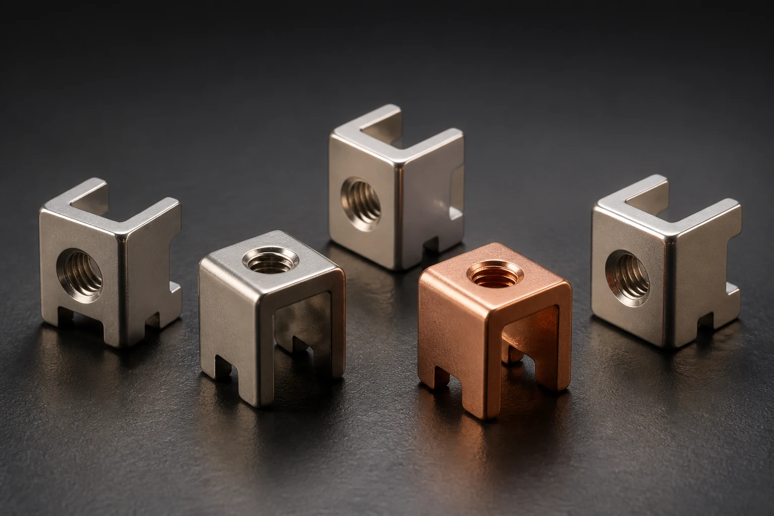
A solder joint and land establish electrical connection; they should not be assumed to support the harness. A reliable assembly gives cable pull, twist and tolerance an independent path into the enclosure or support instead of the PCB copper foil.
Draw the force path from the terminal to the first restraint
Mark terminal direction, conductor size, insulation diameter, bend radius, first restraint, enclosure pass-through and allowed movement. A distant restraint magnifies terminal bending moment, while an over-constrained cable can lock thermal expansion and assembly tolerance into the joint.
Validate electrical joining and mechanical restraint separately
Terminal drop, rise and solder condition are electrical gates. Cable pull, flex, vibration and clamp retention are mechanical gates. Run them on the same assembly configuration, then remeasure resistance and inspect the land.
- Check lateral force and insertion posture at maximum and minimum harness tolerance
- Verify clamps, ties, sleeves and enclosure edges do not damage insulation
- After service removal, recheck terminal position, solder joints, grounding and restraint
An RFQ needs the harness, not only the terminal drawing
Provide PCB stack-up and lands, terminal drawing, cable specification, crimp or solder process, exit direction, restraint, assembly sequence, environment, pull or vibration program, sampling and packaging. IPC/WHMA-A-620E provides cable and harness workmanship context; the project must still define mechanical loads.
Apply this guide to a project
Use product pages to identify the hardware family and the calculator for early estimates only. Acceptance depends on drawings, operating conditions and project tests.