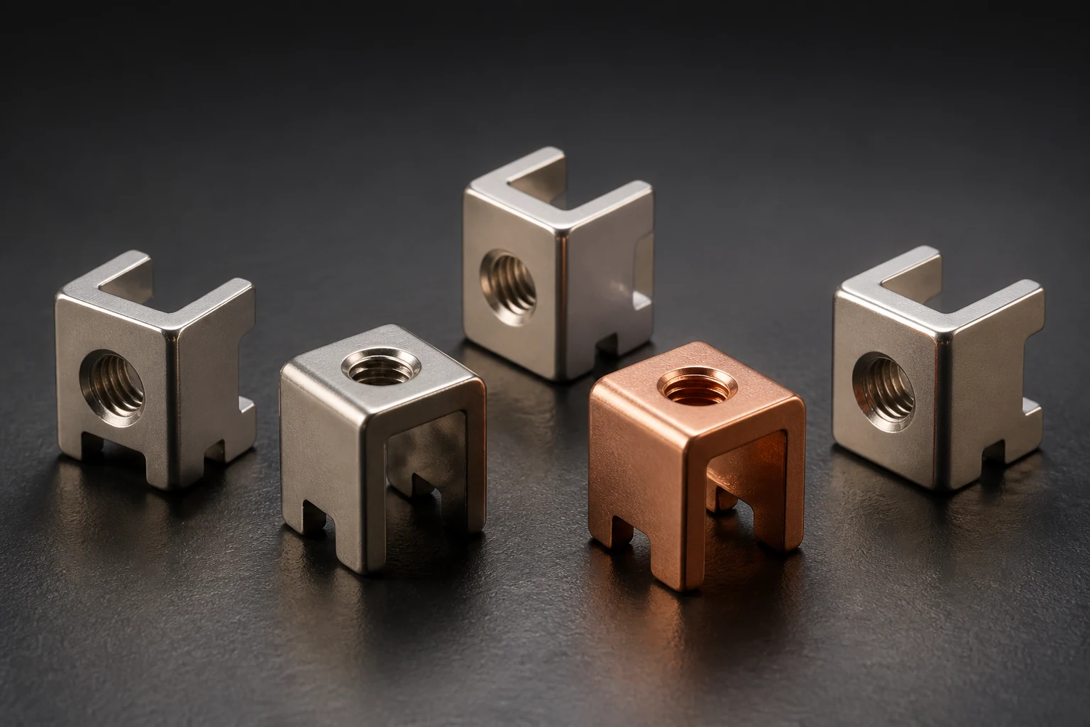
For harnesses connected to PCB power terminals, match the actual wire, crimp terminal and tooling before checking height, mechanical retention and electrical performance. Wire crimps and PCB solder joints are separate interfaces with separate acceptance. Appearance or maximum pull force alone cannot release the whole connection.
Freeze wire and tooling before defining height limits
TE's process-monitoring documentation uses crimp height for analysis. Its specific terminal study also identifies lubrication, tooling condition and measurement-method differences as relevant to height. Monitoring limits must represent the actual product and tooling.
We recommend matching wire identity, conductor construction and section to terminal part number, approved wire range and tooling revision. Specify stripping, conductor crimp and insulation support separately. Similar wire diameters do not establish interchangeability, and one barrel's height tolerance cannot qualify another.
Specify measurement and retain setup-change records
We recommend agreeing locations, gauges and sampling with the terminal supplier, distinguishing conductor and insulation measurements. Compare gauge and section results only through validated methods; do not mix different methods into one unqualified process dataset.
Review agreed samples after first setup, wire changes, die replacement or maintenance. Retain missing strands, conductor damage, positioning errors and height exceptions for the crimp owner's investigation. Follow approved lubricant identity and application; a study of specific TE products cannot authorize extra oil on every terminal.
Record pull-test failure location alongside electrical checks
TE's study separately used four-terminal resistance measurement and pull comparisons. We recommend agreeing fixture, direction, speed and criteria on independent harness specimens, recording strand pullout, wire fracture or terminal-body damage. Do not use PCB pads to carry destructive loading for wire-crimp acceptance.
Define electrical locations and fixtures without treating the combined resistance of crimps, mating contacts, bolts and board soldering as a single crimp value. Agree before-and-after checks and specimen disposition for environmental validation. Maximum pull force does not establish resistance or long-term temperature rise; use product and project requirements.
- Match wire, wire-end terminal and tooling
- Freeze measurement and setup-review methods
- Separate crimp, board and electrical/mechanical acceptance
Frequently asked questions
Is greater pull force always a better crimp? Meet mechanical and electrical requirements rather than maximizing one number.
Does a qualified PCB solder joint prove a qualified harness crimp? The interfaces use different materials, tools and criteria; confirm them independently.
RFQ inputs for wire-end and board interfaces
Supply wire and crimp-terminal identities, tooling information, PCB terminal drawings and connection method. Identify height, pull, resistance or temperature-rise bases, separating harness and PCB assembly responsibilities. Review unresolved combinations before specifying universal height, pull or current values.
Apply this guide to a project
Use product pages to identify the hardware family and the calculator for early estimates only. Acceptance depends on drawings, operating conditions and project tests.