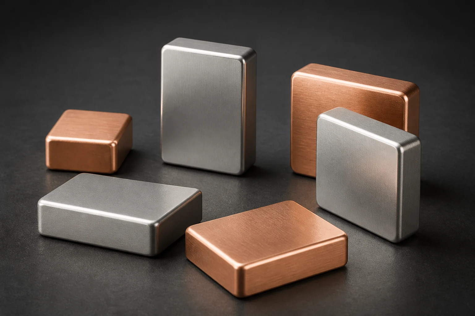
SMT busbar soldering is rarely a single problem of too much or too little paste. Part thermal mass, underside geometry, pad segmentation, stencil release, board warp and the reflow profile act together. Validate stencil and oven choices on the real PCB and orientation.
Start with segmented pads and observable joints
Divide large lands into printable, ventable regions with visible wetting, then define solder-mask bridges, non-solder areas and inspection windows. Underside grooves, locating tabs and height differences change transfer and self-alignment, so apertures should not simply scale the part outline.
Stencil thickness and local apertures serve the full-board process window
Busbar paste demand can conflict with fine-pitch devices. Evaluate aperture zoning, step stencils or a second print while checking area ratio, release, bridging and cleaning. Measure profiles near the busbar and temperature-sensitive components rather than relying on oven settings.
- Record printed paste area, volume and offset
- Inspect placement height, underside support, post-reflow coplanarity and visible wetting
- Use cross-sections or an approved non-destructive method to sample voids, distribution and interface condition
The DFM pack should connect the part, PCB, stencil and profile
Provide the underside drawing, material and finish, mass, coplanarity, land and mask data, stencil revision, paste, placement orientation, support fixture, target profile and acceptance method. IPC-7525C and IPC-7530B supply stencil and profiling frameworks; they do not automatically prescribe a final aperture ratio for a specific busbar.
Apply this guide to a project
Use product pages to identify the hardware family and the calculator for early estimates only. Acceptance depends on drawings, operating conditions and project tests.