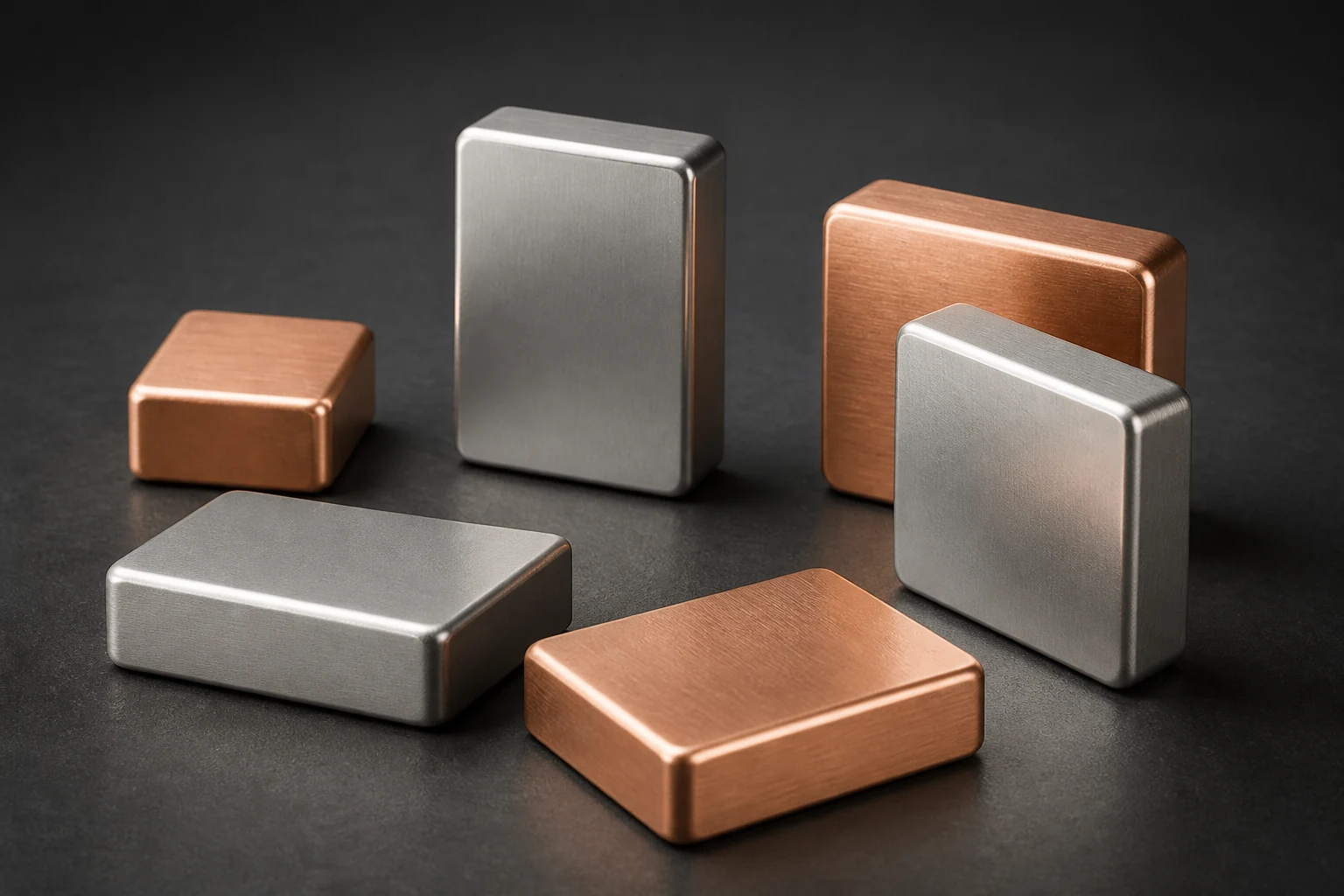
Selecting tin or silver for a copper busbar joint requires the substrate, mating surface, clamping conditions and environment to be reviewed together. ASTM B896-26 includes surface treatment, plating, contact force and contact resistance in its evaluation of conductor connectability. The coating name or color alone cannot predict the assembled joint.
Define a joint that can be reproduced
Identify the copper grade and temper, coating metal and layers, thickness and measurement location, mating finish, washers, fastener, clamped length and contact area. Contact resistance depends on real conductive contact spots and surface-film condition. Nominal overlap area is not the same as effective conducting area.
Copper Development Association connector guidance discusses oxide films, diffusion and barrier layers at an interface. These are design variables, not a universal thickness or life specification for a particular product.
Compare finishes under the intended environment and assembly
Evaluate tin and silver against service temperature, humidity or corrosive media, whether the joint remains stationary, maintenance frequency, mating material and cost. A coating system also includes substrate preparation and any underplate. Changing one of these can alter diffusion, sensitivity to contact pressure and the process window.
The purchase specification should identify the coating system, thickness method, functional faces, hole edges and cut edges, lot evidence and change-notice rules. Without representative environmental and assembly tests, do not describe either finish as universally better.
Retain contact force and loading conditions in resistance tests
ASTM B896-26 evaluates conductor contact resistance against contact force and also covers fretting sensitivity and compressive relaxation. ASTM B539-20(2026)e1 provides methods for static electrical connection resistance at loading levels that include dry circuit and rated current. The methods support comparison; the project defines its acceptance limit.
Fix the torque or preload window, surface cleanliness, voltage taps, current and temperature before testing. After the specified thermal or corrosion exposure, retest the same joint structure and report disassembly or retightening. Resistance values measured at different clamping forces are not directly comparable.
- Use representative copper, plating, washers and mating material
- Report contact force or tightening procedure and four-wire measurement points
- Pair initial results with post-exposure resistance, appearance and joint condition
Limit the conclusion to the conditions that were tested
A passing record covers the material lots, coating, joint geometry, clamping conditions and environment in that test. When the finish or fastener stack changes, determine whether the existing evaluation still applies.
Apply this guide to a project
Use product pages to identify the hardware family and the calculator for early estimates only. Acceptance depends on drawings, operating conditions and project tests.