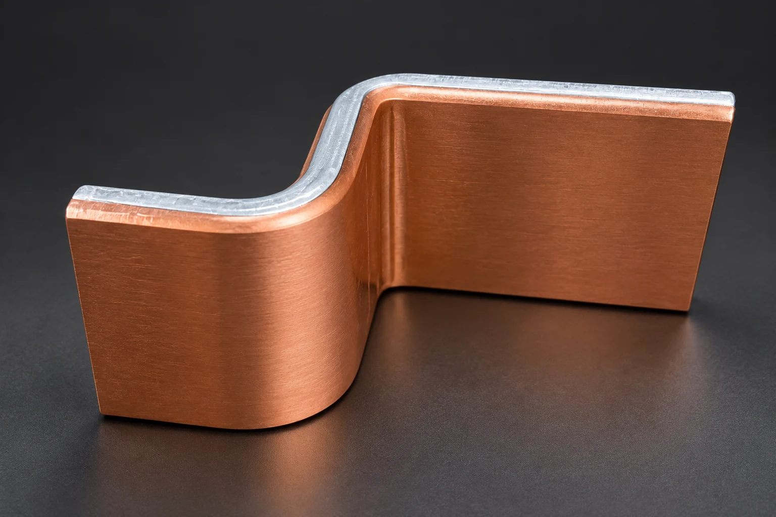
Check retained material layers, loading direction and the original area used to calculate stress before interpreting a Cu-Al busbar tensile report. A whole composite-section tensile result is not directly an interface bond-strength result. A local specimen also does not automatically represent the finished busbar.
Link sampling to the inspection objective
ASTM E8/E8M-25 covers room-temperature metallic tensile strength and ductility measurements and cautions that selected specimens may not represent a complete product or service behavior. We recommend identifying batch, location, loading direction and whether sampling precedes or follows forming, welding or heat treatment.
Have the laboratory confirm specimen applicability and retain before/after section drawings. If preparation removes copper, aluminum or a joining region, state the tested object explicitly rather than describing it as the unchanged composite.
Record original area and gauge length
We recommend retaining initial dimensions, measurement positions and area calculations, including which layers enter a composite-area result. Record separately tested layers separately. Do not rank results with different area definitions or infer layer strength from the Cu-Al ratio without a validated model.
Check initial gauge length, elongation measurement and specimen form. E8 and E8M differ in gauge-length requirements for some specimens; unit conversion alone does not make conditions equivalent. The laboratory must confirm geometry, rate and validity against the agreed complete method.
Connect traces to fracture observations
Request original force/displacement or stress/strain records and result-reading methods. Record fracture positions and photographs, including gauge-section fracture, grip abnormalities or layer separation. Have the laboratory assess validity when gripping is abnormal; do not edit away anomalies to obtain a passing trace.
If interface observation is required, commission section inspection separately. ASTM E3 emphasizes metallographic specimen location and orientation; relate the observation plane to the fractured region. Keep tensile, interface-specific and metallographic conclusions separate, without turning them into a generic life estimate.
- Record retained layers and direction
- Confirm original area and gauge length
- Link original traces to fracture positions
Frequently asked questions
Does high tensile strength prove a reliable interface? Whole-section loading and interface bonding need their own methods and criteria.
Can two MPa values be compared directly? First check specimen condition, area, direction and method.
RFQ and laboratory inputs
Provide composite structure, material condition, processing history and sampling drawings. Identify whole-section or interface objectives, specimen form, area definition, reporting and decision ownership. Review samples before promising an unsupported universal strength value.
Apply this guide to a project
Use product pages to identify the hardware family and the calculator for early estimates only. Acceptance depends on drawings, operating conditions and project tests.