Material weight and price are the easiest parts of a Cu-Al discussion. The project is decided by the less convenient questions. How will current cross the terminal area? Can moisture reach an exposed aluminum edge? Will punching or bending disturb the bonded interface? A replacement becomes credible when those conditions are defined.
Define the replacement target
Cost, weight and supply stability create different design spaces. A weight target may allow copper to remain at critical interfaces. A fixed installation envelope requires resistance and temperature-rise checks before the material ratio is selected. The minimum input should include continuous and peak current, allowable temperature rise, ambient temperature, space and connection method.
Avoid a single current-density rule
Copper provides high electrical and thermal conductivity. Introducing an aluminum core changes resistance and the heat-flow path for the same external geometry. Calculate the actual section, length and layer ratio, then validate the installed orientation, spacing, surface condition and cooling. Published Copper Development Association data also show that busbar ampacity changes with spacing, number of bars, emissivity and allowable temperature rise.
Design the terminal interface
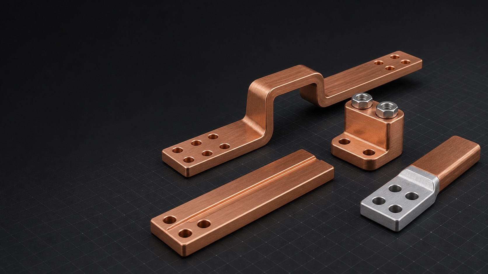
The middle section carries current while the terminal transfers it into a bolt, terminal or device interface. Copper layer thickness, hole edge distance, clamping zone and plating boundary should be defined on the drawing. Exposed aluminum edges need a sealing strategy. Oxides, grease, paint and other high-resistance layers on mating surfaces also require controlled surface preparation.
Treat moisture as a design input
Copper and aluminum form a galvanic couple when an electrolyte is present. NASA testing of sealed and unsealed aluminum-copper couples found no substantial corrosion in the sealed sample and considerable corrosion in the unsealed sample. Edge exposure, sealing continuity, drainage, fasteners and washers therefore belong in the material decision.
Validate the manufacturing route
Punching, milling, bending and welding load the bonded interface in different directions. Define bond orientation, permitted processing areas, bend radius and end preparation. Prototype checks can include sections, edges, hole walls and bend exteriors, followed by dimensional inspection, DC resistance, temperature rise and environment tests selected for the real application.
Compare total part cost
Material savings are only one line. End copper, sealing, plating, dedicated tooling, additional inspection and scrap all affect the finished part. Compare complete process quotations for the copper and composite options. Early pilot validation is more reliable than a volume saving estimate while interfaces and environment remain open.
Apply this guide to a project
Use product pages to identify the hardware family and the calculator for early estimates only. Acceptance depends on drawings, operating conditions and project tests.