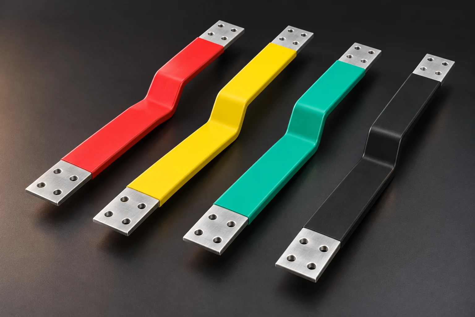
Estimate free thermal expansion, then examine how supports and equipment terminals constrain movement. Use a validated flexible section or support arrangement to accommodate motion while maintaining specified electrical-joint clamping. Loosening terminal bolts is not a thermal-movement solution.
Reference temperature changes to installation
For an initial free-expansion estimate, ΔL = α × L × ΔT. L is the relevant directional length and ΔT is the change from installation to an operating or environmental extreme. Check heating and cooling, including relative movement of terminals, frames and conductors.
Use segmented estimates or an approved thermomechanical model for a non-uniform temperature field. Cabinet air temperature is not automatically the temperature of every conductor segment.
Use copper and aluminium values only as preliminary references
Table 1 of CDA and European Copper Institute's Copper for Busbars gives typical expansion coefficients of about 17 × 10⁻⁶/K for copper and 23 × 10⁻⁶/K for aluminium. A hypothetical uniform 1 m conductor heated by 60 K would freely extend by about 1.02 mm or 1.38 mm respectively.
These are pure-material examples. Composite response also depends on layer geometry, bonding and restraint. Establish it from confirmed supply data, specimens or a validated model rather than averaging those coefficients into a finished-product guarantee.
Give locating points and flexible sections distinct roles
Draw locating points, other supports, permitted directions and terminal load limits. Review the flexible section's installed length, shape, movement capability and insulation clearances. Its current, temperature-rise and fault-duty requirements remain applicable.
Section 6.6.5 of Copper for Busbars warns that longitudinal expansion can cause joint slip and loosening and calls for flexibility elsewhere in long runs. Identify where movement is intended instead of treating a conventional bolted overlap as a sliding joint.
- Check cold, hot and tolerance combinations for relative terminal displacement
- Check clearances around insulation, holes and edges throughout movement
- Record support reactions, terminal loads and electrical-joint condition before and after cycling
Frequently asked questions
Will an elongated hole solve expansion? Suitability depends on whether the location provides positioning, support or electrical contact; direction and clamping need design review.
Can support checks be omitted after adding flexibility? The mechanical boundary has changed. Recheck support, fault loads and clearances in that configuration.
Supply the thermomechanical boundary for quotation
Provide route, composite section, installation range, conductor temperatures, frame and terminal materials, locating points, permitted movement and loads. Test with actual supports and terminals, checking deformation, joint resistance, clamping and insulation position after cycling.
Apply this guide to a project
Use product pages to identify the hardware family and the calculator for early estimates only. Acceptance depends on drawings, operating conditions and project tests.