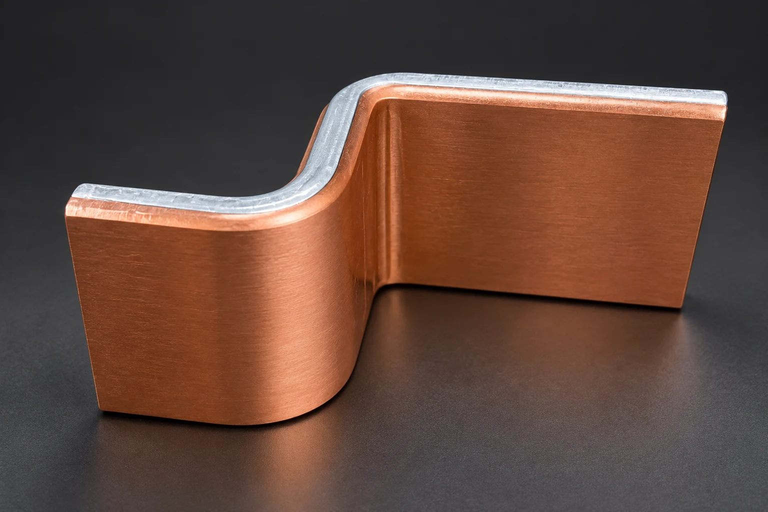
A formed Cu-Al busbar procurement drawing should define functional datums, tolerances and inspection state. Passing hole diameter does not prove that a complete hole pattern will fit. Agree the drawing revision and measurement method before releasing samples.
Start with the installed locating features
We recommend identifying mounting faces, locating holes and mating terminals, with each locating role stated. Make copper orientation, machined edges and insulation regions distinguishable so inspection does not start from the wrong face.
ISO 5459:2024 covers datum indication and interpretation. Its public scope explicitly excludes the verification operator; a datum definition does not itself prescribe fixtures, sampling points or measurement calculations.
Specify holes, mating surfaces and the envelope separately
ISO 1101:2017 defines geometric-specification symbols and interpretation. Where geometric tolerancing is used, the designer must specify the adopted system, datums and requirements fully. Hole diameters and chained dimensions may leave the intended fit insufficiently defined.
We recommend separate requirements for hole size, pattern position, mating surfaces, formed height and installed envelope. Identify features that constrain fit, seating or insulation before agreeing manufacturable and inspectable tolerances. Avoid imposing the same unnecessarily tight tolerance everywhere.
Match inspection state and file revision
State whether acceptance follows forming, finishing or insulation, and whether measurement is free-state or under agreed restraint. Document any flattening fixture and method so applied force does not hide a free-state deviation. Delivered holes and mating surfaces must correspond to the specified state.
Bind drawing, model, inspection checklist and first-article report to one revision and define file precedence. Mark affected characteristics after changes to layers, holes, bends or insulation, review retests and retain previous versions and approvals.
- Identify locating features, layer direction and delivered state
- Agree fixtures, methods and functional tolerances
- Match drawing, model and inspection-report revisions
Frequently asked questions
Is a 3D model alone enough for acceptance? It must carry or be accompanied by complete specifications, including accessible tolerances and inspection references.
Does a passing caliper hole-spacing check cover the drawing? Use the specified characteristics and methods. One dimension does not replace position and form requirements.
RFQ package for drawing review
Provide the current drawing and model, counterpart terminals, installation constraints, composite section, process sequence and inspection checklist. Identify adjustable requirements, agree sample measurements and fit checks, then freeze production acceptance rules.
Apply this guide to a project
Use product pages to identify the hardware family and the calculator for early estimates only. Acceptance depends on drawings, operating conditions and project tests.