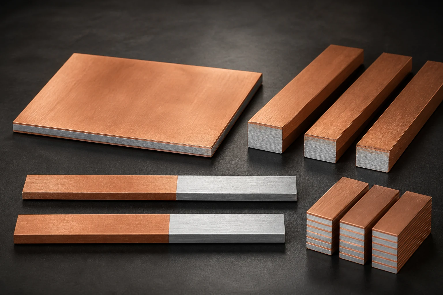
Review overlap length, hole layout and clamping together, then validate the actual Cu-Al joint. Longer overlap or additional bolts alone cannot establish acceptance. Start with a drawing of both mating surfaces, layer orientation and current path.
Separate the mating surface from projected overlap
Identify copper and aluminium faces, counterpart material, finish and insulation setback. We recommend marking the nominal overlap separately from the available mating region, including holes, steps and areas that do not seat correctly.
Copper for Busbars separates copper DC joint resistance into current-spreading and interface contributions. Its homogeneous-copper curves and bolting tables are not acceptance specifications for layered Cu-Al conductors.
Review holes and clamping coverage on one drawing
The copper guide describes how holes disturb current flow. For composite reviews, retain each layer's thickness, machined edges and connection direction rather than comparing projected area alone.
We recommend comparing installation access, edge distances, washer bearing regions and seating. Slots or changed hole diameters require review of adjustment, insulation and support conditions. Do not enlarge holes during installation without approved disposition.
Freeze the complete joint for sample validation
Record both conductors, finishes, fasteners, washers, assembly sequence and approved tightening method. Include production cleaning and assembly steps so tested and delivered joints share more than their outline.
Keep resistance measurement points fixed. Retain initial results, connection-zone temperature rise under the intended load and project-required post-exposure retests. AC circuits also require frequency and arrangement inputs. Set acceptance through the equipment requirements and approved test plan.
- Draw mating materials, layer direction and holes
- Trace the full fastening combination and samples
- Keep measurement points, load and retest rules fixed
Frequently asked questions
Can overlap always equal bar width? The specific configuration and load need validation; no universal proportion is supplied here.
Do additional bolts reduce qualification work? The holes and clamping configuration have changed. Review affected tests rather than inferring current capacity from bolt count.
RFQ inputs for joint layout
Provide both terminal drawings, composite section, hole and finish requirements, load, access envelope, fastening stack and acceptance plan. Include comparable reference-joint data when available, then agree sample configurations before freezing the drawing.
Apply this guide to a project
Use product pages to identify the hardware family and the calculator for early estimates only. Acceptance depends on drawings, operating conditions and project tests.