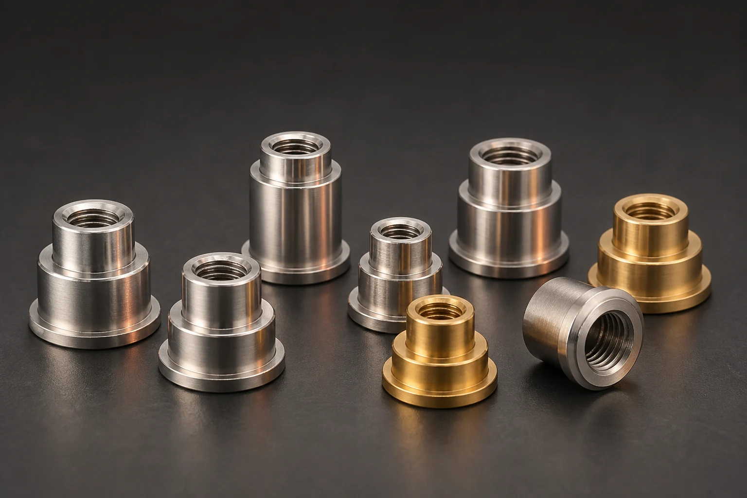
Accept SMT nut and standoff threads using gauges matched to the drawing's system, tolerance and delivery condition. Trying a normal screw assists assembly checks but does not replace GO/NO-GO inspection. Separate incoming and post-reflow records to distinguish contamination, bottoming and solder-joint loading.
Record thread and gauge identity
ISO 1502 covers general-purpose metric thread gauges and gauging. OSG explains matching drawing accuracy and distinguishing current/legacy gauge markings. We recommend recording diameter, pitch, tolerance, standard and plated delivery state, plus gauge identity and calibration status.
Use applicable gauges and acceptance rules for other thread systems; do not copy one NO-GO entry rule into every system. An M label or mating screw alone does not complete acceptance requirements. Recheck the program after size changes instead of reusing the previous batch's setup.
Separate threads, bore and effective depth
OSG specifies hand gauging without excessive force and distinguishes thread limit gauges from plain bore plug gauges. Follow the approved procedure and record both ends. Investigate cleanliness, alignment and gauge condition when blocked, rather than using a wrench to force entry.
Check effective thread length and bottom clearance on blind holes against the drawing. Partial GO entry does not establish that the intended screw avoids bottoming. Have the inspector confirm access and criteria for short threads; retain bore, depth and interference results separately.
Define independent post-reflow conditions
We recommend recording incoming, post-reflow and relevant post-rework states, including paste, reflow and cleaning revisions. Inspect openings and residues before gauging and have the assembler approve cleaning. Use traceable comparative samples to locate changes rather than attributing every post-reflow obstruction to incoming quality.
Use reviewed board support and handling without unapproved rotational loads on solder joints. Thread gauges do not establish pad peel resistance, standoff torque resistance or permitted screw torque. Validate these on the assembly and isolate abnormal parts; gauges are not rework tools.
- Match gauge system and tolerance
- Check bore and effective depth separately
- Separate incoming and post-reflow records
Frequently asked questions
Can a screw reaching the bottom replace gauging? Screw tolerance and wear differ; use specified gauges.
Does a post-reflow GO pass establish tightening torque? Verify thread, hardware and board-connection load capacity separately.
RFQ and board-assembly inputs
Provide thread system, tolerance, effective depth and plating requirements with pad, reflow and screw plans. Agree gauge rules, stages, board support and abnormal-part handling, separating supplied thread acceptance from assembled-connection validation.
Apply this guide to a project
Use product pages to identify the hardware family and the calculator for early estimates only. Acceptance depends on drawings, operating conditions and project tests.