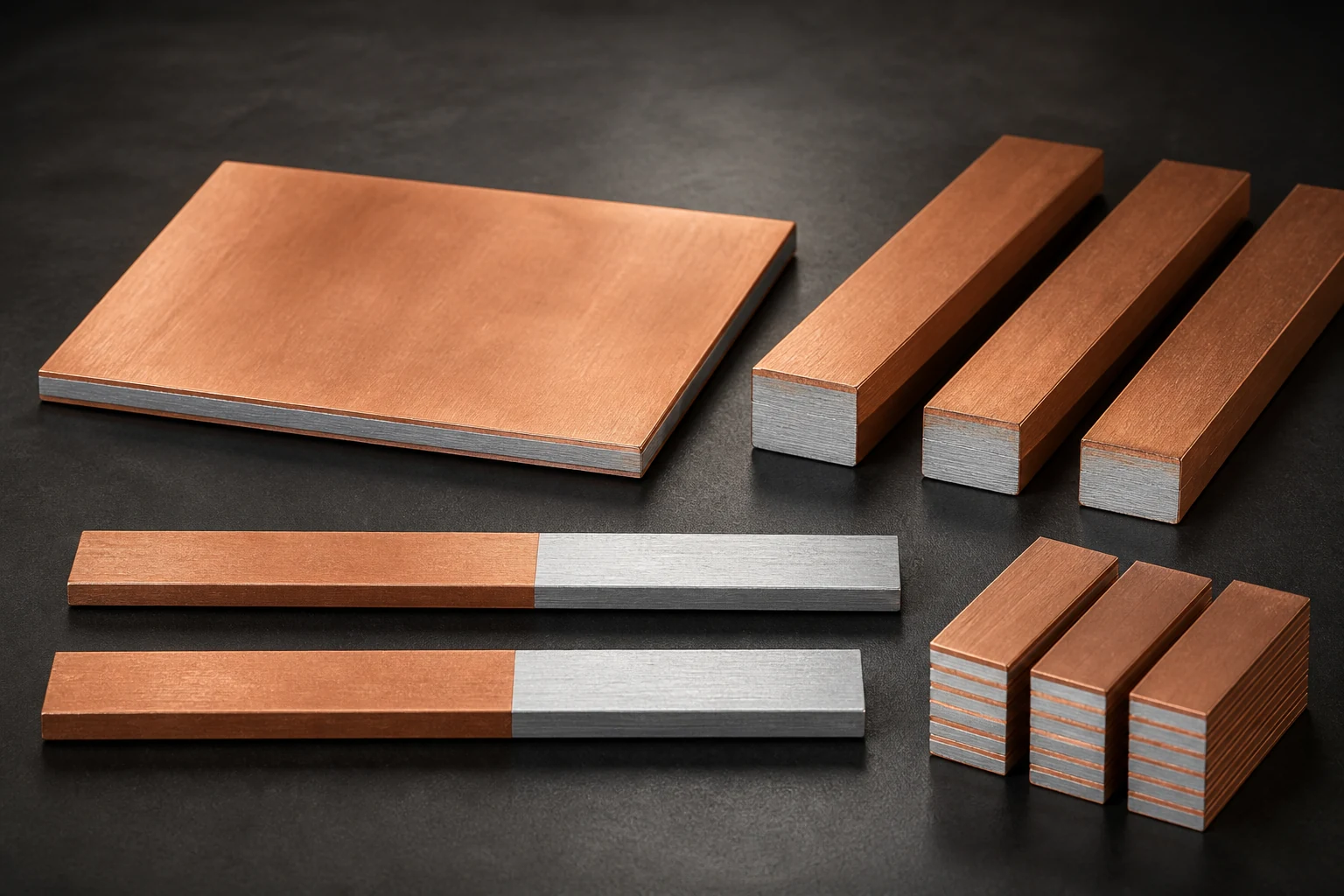
Coordinate a Cu-Al busbar and fuse against normal load, prospective faults and withstand throughout interruption. Equal current ratings do not establish equivalent protection. Obtain the selected fuse's data at the actual voltage and circuit conditions before reviewing the bar, joints and supports.
Define the fault circuit and protected region
We recommend a single-line diagram identifying supplies, fuses, bars, parallel branches and fault locations. State maximum operating voltage, AC or DC service, prospective fault current and relevant DC time constant or AC conditions. Do not assume a downstream fuse covers an upstream fault.
Eaton relates interrupting capability to safely clearing fault current at rated voltage. Its 250FM page separates AC and DC conditions and lists clearing I²t at different voltages. This illustrates the need for conditional data, not a recommendation of that fuse for every bar.
Distinguish melting and total-clearing integrals
Eaton distinguishes total-clearing I²t as the sum of melting and arcing integrals. I²t is expressed in A²s, not directly in joules of joint heat. Withstand evaluation through fault clearing must not omit the arcing interval by considering melting data alone.
Request applicable total-clearing and peak let-through data. Have the protection engineer review the limiting region, lower fault currents and overload coverage. Use valid evidence for the composite section, layer ratio, joints and insulation; do not directly adopt a pure-copper conductor thermal constant.
Record thermal and structural checks separately
We recommend separate thermal-withstand evidence and support, fastener and joint checks against peak fault current. Passing an I²t comparison alone does not qualify the mechanical assembly. Review actual layer spacing, conductor separation, support spans and installation state.
Also review ambient temperature, connection heating, startup and repeated pulses during normal service. A fuse does not replace continuous temperature-rise validation. Fault tests require qualified facilities and an approved safety plan; do not deliberately short a field installation.
- Define fault locations and AC or DC interruption conditions
- Retain clearing I²t and peak data with their applicability
- Review composite thermal withstand, joints and supports separately
Frequently asked questions
Can another fuse with the same amperage be released without review? Recheck voltage, interruption, operation and limiting data, installation and thermal conditions.
Does fast operation guarantee protection? Establish that the complete clearing event stays within the bar and joint limits.
RFQ inputs for protection coordination
Provide the single-line diagram, fault assessment, fuse identity and data, bar section, joints, insulation and support layout. Identify existing evidence and needed analysis or testing before agreeing samples and production checks. A material quotation cannot establish system protection coordination.
Apply this guide to a project
Use product pages to identify the hardware family and the calculator for early estimates only. Acceptance depends on drawings, operating conditions and project tests.