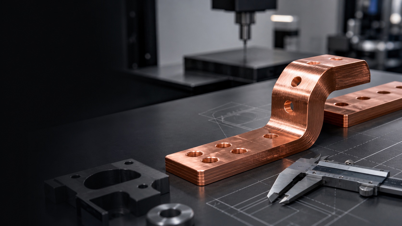
Temperature rise is the difference between specimen temperature and a defined ambient reference, not simply the hottest colour in a thermal image. Load profile, mounting, cooling, measurement points and stabilization criteria must all be fixed for selection or acceptance data.
Use the application to define load and thermal boundaries
Record continuous current, pulses or ripple, energization time, ambient temperature, airflow or coolant, neighbouring heat sources and mounting orientation. Cabinet bars, board-level SMT busbars and liquid-cooled terminals should not share a context-free empirical rise value.
Thermocouples, thermal images and voltage drop answer different questions
Thermocouples provide fixed-point histories. Thermal imaging reveals spatial hot spots but shiny metal can reflect its surroundings because of low emissivity. Four-wire drop helps identify local contact-resistance change. Align all three against the same load timeline.
- Place repeatable points at interfaces, conductor midpoints, ends and nearby insulation
- Record the ambient reference and the full heating curve before stabilization
- Recheck torque, drop and appearance before and after the run
Reports should let another laboratory reproduce the test
Include part revision, materials and finish, torque, cables or PCB, fixture, sensor attachment, load program, environment, instruments, sample interval and stop rule. IEC 60947-1 provides product-standard context for terminal temperature rise, but the applicable project and equipment requirements still set acceptance limits.
Apply this guide to a project
Use product pages to identify the hardware family and the calculator for early estimates only. Acceptance depends on drawings, operating conditions and project tests.